
Page 74 - CAT-027-6 IT.TE.DI. Catalog
P. 74
PCD/CBN
TEDI MILL - ASSEMBLY PROCEDURE
FOR INSERTS
4
3
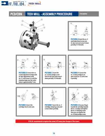
PICTURE B Connect the no. 3 axial adjustment wedge with its own adjustment screw
(no. 4 ) and screw it in until the maximum gap over the cutter body is approximately 1 mm.
1
PICTURE E Insert the cartridge into its own seat.
6
PICTURE A Insert the no. 4 axial adjustment screw into its own seat and screw it down partially (1-2 threads).
5 6
3
41
5
2
6
PICTURE C Insert the
no. 6 clamp wedge screw into its own seat and screw it down partially (1-2 threads).
2
PICTURE F Insert the no. 2 cartridge clamping screw and screw it down partially.
PICTURE D Connect the no. 5 clamp wedge to its own screw (no. 6 ) and screw it partially.
IT.TE.DI. recommends to replace the screw (n°2) every two changes of the insert.
74
4
3 2
6
PICTURE G Use your finger to push the cartridge towards the no. 3 wedge and tighten the no. 2 clamping screw. Then you can tighten the
no. 6 clamp wedge screw.
