
Page 73 - CAT-027-6 IT.TE.DI. Catalog
P. 73
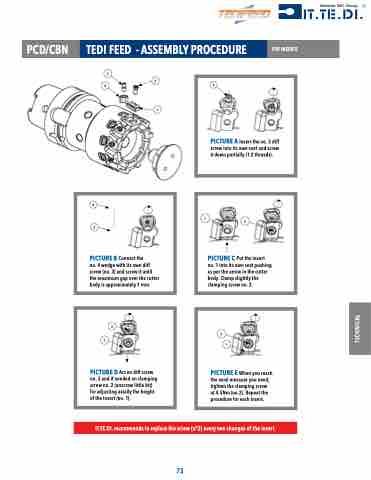
                                                                   PCD/CBN TEDI FEED - ASSEMBLY PROCEDURE
3 43
1
FOR INSERTS
  2
  PICTURE A Insert the no. 3 diff screw into its own seat and screw it down partially (1-2 threads).
      4
3
1
2
PICTURE C Put the insert no. 1 into its own seat pushing as per the arrow in the cutter body. Clamp slightly the clamping screw no. 2.
  PICTURE B Connect the
no. 4 wedge with its own diff screw (no. 3) and screw it until the maximum gap over the cutter body is approximately 1 mm.
      3
1
2
1
 PICTURE D Act on diff screw no. 3 and if needed on clamping screw no. 2 (unscrew little bit) for adjusting axially the height of the insert (no. 1).
PICTURE E When you reach the axial measure you need, tighten the clamping screw at 4.5Nm (no.2). Repeat the procedure for each insert.
 IT.TE.DI. recommends to replace the screw (n°2) every two changes of the insert.
73
TECHNICAL
